
|

|
|
|
Bob Leffler's RV-10
|
Date: 6-21-2011
|
Number of Hours: 1.00
|
Manual Reference: OP38-3, OP38-4
|
Brief Description: Aileron Trim #2
|
|
OP38-3, Step 1, 2, 3, & 4
Before installing the Aileron Trim Servo, Final-Drill the four 1/8" mounting holes in the servo fiange with a #28 drill.
Using two clevis pins and two W-1033B Aileron Trim Links, attach the ES-MSTS-6A Aileron Trim Servo to the W-1033C Aileron Trim Arm.
Insert the snap bushing in the 3/8" hole in the side of the Aileron Trim Actuation Assembly. Carefully feed the servo wire bundle through the snap bushing.
Align the four holes in the mounting fiange of the ES-MSTS-6A Aileron Trim Servo with the four holes in the Aileron Trim Actuation Assembly and fasten the subassembly together using the hardware called out.
OP38-4, Step 1, 2, 3, & 4
Align the Aileron Trim Actuation Assembly with the W-822PP Wing Access Plate. Verify that aileron trim actuation assembly is positioned on the interior surface of the wing access plate.
Match-Drill the four 5/32" holes in the Aileron Trim Actuation Assembly into the W-822PP Wing Access Plate with a #19 drill.
Separate the Aileron Trim Actuation Assembly from the W-822PP Wing Access Plate and final-drill the eight nutplate attach rivet holes in the aileron trim actuation assembly with a #40 drill.
Deburr all sixteen holes in all parts and dimple the four #19 holes in the Wing Access Plate for #8 flush-head screws. Dimple the nutplate rivet holes and the eight nutplate attach rivet holes on the bottom side of the Aileron Trim Actuation Assembly for 3/32" flush-head rivets.
I also connected the wiring to a DB-9.
|
|
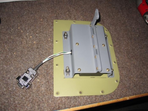
Aileron Trim Actuation Assembl
|
|
|
|
|
|
|
|
|
Copyright © 2001-2024 Matronics. All Rights Reserved.
|