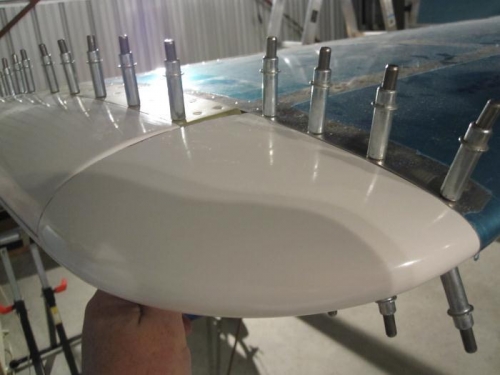
Trim the width of the molded flange on the HS-910 Horizontal Stabilizer Tip Fairing if required to meet the dimensions given. Progressively trim away the aft edge of the horizontal stabilizer tip fairing to leave a minimum 1/8 inch gap between the aft edge of the tip fairing and the forward face of the elevator counterbalance arm. It will be necessary to temporarily attach the elevator to the horizontal stabilizer assembly. I completed the right side.
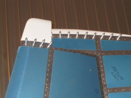
Match-Drill the HS-910 Horizontal Stabilizer Tip Fairing to the HS-1001 Horizontal Stabilizer Skin in a similar manner as the elevator and rudder.
12-4, Steps 1 & 2
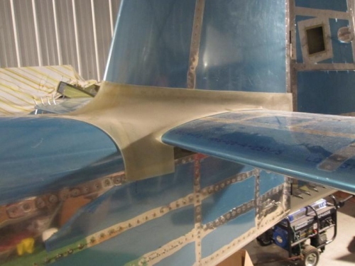
Trim the width of the molded flange on the VS-1 009 Vertical Stabilizer Tip Fairing if required to meet the dimensions given. Trim away the aft edge of the vertical stabilizer tip fairing so the aft edge is parallel and flush with the vertical edge on the VS-1001 Skin. This will provide a minimum 1/8 inch gap between the aft face of the vertical stabilizer tip fairing and the forward face of the rudder counterbalance arm.
Match-Drill #30 and cleco the VS-1 009 Vertical Stabilizer Tip Fairing using the holes in the VS-1001 Vertical Stabilizer Skin as a drill guide. Work from front towards the trailing edge.