
|

|
|
|
Bob Leffler's RV-10
|
Date: 12-30-2010
|
Number of Hours: 4.00
|
Manual Reference: 41-8, 46-2, 46-3
|
Brief Description: Engine Mount and Main Tire Assembly
|
|
41-8, Step 6
Cleco the shims and aft hinge segments to the fuselage. Insert the hinge pins into the aft hinge segments as this will keep the hinge eyelets in their proper shape if a mistake is made while riveting.
Instead of installing two hinges on the bottom, I fabricated two aluminum parts to replace the hinges.
46-2, Step 1 & 2
Using a 3/8" bit, final-drill one of the two 3/16" holes in the top of the Firewall Assembly common to the WD-1001-01 Dyna-1 Engine Mount. Temporarily bolt the engine mount to the Firewall.
Align the engine mount with the second 3/16" hole in the top of the Firewall Assembly and final-drill this hole using the same bit. Keep the engine mount in place while drilling to help maintain the alignment of the bit. Secure the engine mount to the Firewall Assembly, then final-drill the remaining four holes. Place a bolt in the holes after each is drilled.
Remove the WD-1001-01 Engine Mount from the Firewall Assembly, deburr the holes in the Firewall Assembly, then permanently bolt the engine mount.
46-3, Steps 1, 2, & 3
Pull the bearings from the Main Wheel Assembly by removing the snap-rings that are retaining them. Pay close attention to how the bearings, grease seal rings, and grease seal felts are installed so that they can be reinstalled in the same way.
Split the Main Wheel Assembly by removing the bolts holding the Brake Disk and the Inner and Outer Wheel Halves together.
Dust the U 15X6.0-6IT Tube and the inside of the U 15X6.0-6 Tire with talcum powder, then mount the tube and tire on the Inner and Outer Wheel halves. The red dot on the tire is installed next to the valve stem of the tube. Bolt the wheel halves and the brake disk together. Carefully observe the manufacture's bolt torque specifications shown on the document in the wheel/brake package.
Slowly inflate the tire to 25 psi. Deflate it fully and re-inflate it a couple more times to work out any wrinkles in the tube. The final inflation pressure is 42 psi.
|
|
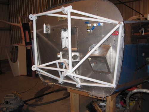
Motor Mount Installed
|
|
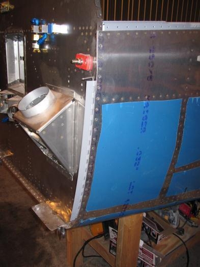
Hinges Riveted and Bottom Plate Fabricated
|
|
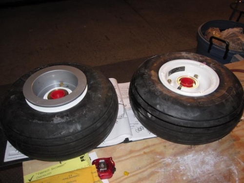
Main Wheels and Tires Assembled
|
|
|
|
|
|
|
|
|
Copyright © 2001-2024 Matronics. All Rights Reserved.
|