
|

|
|
|
Jims RV-8
|
Date: 4-10-2022
|
Number of Hours: 3.10
|
Manual Reference:
|
Brief Description: Right-Side Panel Wiring
|
|
I spent the most time laying out the plan of wiring the right-side panel. The right-side panel will be riveted in place, and while the center panel will be removable, the right-side panel will not, and there are many common wires between the two panels that will need service loops.
I have a good grasp of how the Nuckolls Z-12 electrical diagram functions and relates to the switches, bus bars, and boxes, but running the wiring to make all those functions happen takes more understanding. So, I sketched it out into a picture and then started working on wiring it. I didn't get very far before I stumbled upon the 2-10 vs. P-Mag switch idiosyncracies. They are both DPDT (Double Pole, Double Throw) switches, but the two diagrams are different. One view is looking thru the front of the (2-10 switch) from a front-facing view to see the terminals in the back, while the other (P-Mag switch) is looking at a rear-facing view of the terminals. The P-Mag switch has numbers on the terminals, so I have to trust that those are correct.
Anyway, I made some progress as I cut and drilled the shared bus bar between the two alternator CBs. I will power them separately, but if one power supply is faulty, I have the other supply to fall back on. I also put a section of heat shrink tubing around the two inner posts of the engine start button as they are not needed in my application. Saw that trick on Bob's log.
|
|
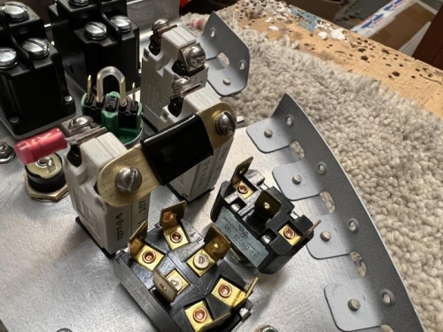
shared bar - Alternator power
|
|
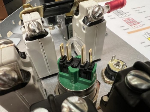
heat shrink the un-needed inner posts
|
|
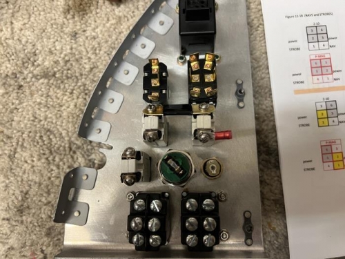
right side panel inching along
|
|
|
|
|
|
|
|
|
Copyright © 2001-2024 Matronics. All Rights Reserved.
|