
|

|
|
|
Bob Leffler's RV-10
|
Date: 2-16-2011
|
Number of Hours: 2.00
|
Manual Reference: 47-02, 47-03
|
Brief Description: Spinner
|
|
47-02, Step 8
Trim the S-601-1 Spinner along the traces
47-03, Steps 1, 2, 3, 4, & 5
Slide the S·601·1 Spinner onto the propeller hub. Progressively trim the cut-outs of the spinner until it clears the propeller blades, through all blade angles, by a 1/16" to 1/8". Be sure the spinner is seated firmly on the propeller hub. When this is the case, the spinner will be in contact with the Spinner Back Plate Assembly.
Mark the locations for the six screws used to secure the S-601-1 Spinner to the S-603 Spinner Front Plate, and mark the locations for the fourteen screws used to secure the spinner to the Spinner Back Plate Assembly.
Hold the S·601·1 Spinner in place by clamping it to the flange of the Spinner Back Plale Assembly. Using a #30 bit, drill pilot holes for Ihe screws that secure the spinner to the S-603 Spinner Front Plate. Cleco while drilling. Drill pilot holes for the screws that secure the spinner to the Spinner Back Plate Assembly. To prevent "pillowing" of the spinner between the screws, start drilling midway between the propeller blade cut-outs working outward toward the cut-outs.
From AS3·063 aluminum sheet, make two S-1001 Gap Fillers and two S-1002 Backing Plates. Once again, make sure there is a 1/16" to 1/8" clearance between the propeller blade and gap fillers. I started rough fitting the first filler, but will need to continue during next session.
|
|
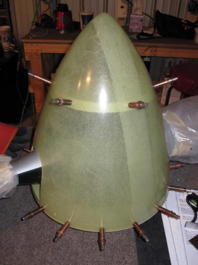
Spinner drilled and clecoed
|
|
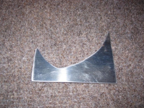
Filler plate rough cut
|
|
|
|
|
|
|
|
|
Copyright © 2001-2024 Matronics. All Rights Reserved.
|