Check that the length of both of the BUSHING 065 X .375 X 2.313 Control Stick Base Bushings is between 2 1/4 inches and 2 5/16 inches. Check that an AN4 bolt will fit the inside diameter of the control stick base bushings and ream if required. Deburr the ends of the control stick base bushings so that they slide easily inside the WD-1011 Control Stick Bases.
The pivot tube of the control stick base must be 1/32 inch to 1/16 inch shorter than the control stick base bushing. File the ends of the control stick base pivot tubes if/as required to achieve the correct length. Deburr the inside edges of the control stick base pivot tubes. Insert a control stick base bushing into each control stick base as shown in Figure 1.
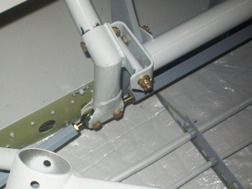
Bolt the WD-1011-L Control Stick Base to the WD-1010 Control Column. If the BUSHING 065 X .375 X 2.313 Control Stick Base Bushing is too long to fit into the control column it must be trimmed along with the control stick base pivot tube to maintain the length differential described in the previous step. Repeat for the WD-1 011-R Control Stick Base.
Install the F-1065 Pushrod Assembly into the WD-1011-Land the WD-1011-R Control Stick Bases. Leave the nuts finger tight.
Install the WD-1012 Control Sticks into the control stick bases. Move the control sticks through their full range of motion and check for interference. NOTE: When F-1043D-L/R Cover Panels are later installed check for interference with control sticks and trim the cover panels if/as necessary for clearance.