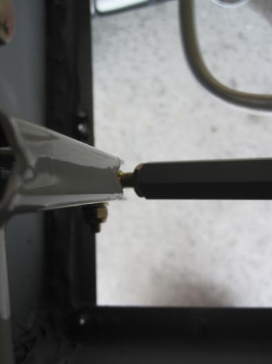
Bolt the F-1064 Aileron Pushrod Assembly to the WD-1014 Torque Tube Assembly. There are two washers called-out; one washer is installed inside the torque tube clevis arm along with the pushrod rod end bearing and the other washer is installed under the nut.
Rig the ailerons. Use the W-730 Bellcrank Jig to set the aileron actuation system (left wing shown) to its neutral position. NOTE: It may not be necessary to remove the bellcrank to aileron pushrod bolt. There should be enough thread protruding from the nut to allow the use of the bellcrank jig.
Insert a WD-1012 Control Stick into the WD-1011-L Left Control Stick Base. Adjust the length of the F-1064 Aileron Pushrod Assembly to obtain a neutral (vertical) control stick position. Tighten the jam nuts when adjustment is complete.
Install the W-730 Bellcrank Jig in the right wing while leaving the first bellcrank jig in the left wing. Install the right side F-1064 Aileron Pushrod Assembly by adjusting its length as required to fit between the WD-1011-R Right Control Stick Base and the WD-1014 Torque Tube Assembly. Since the neutral control stick position was already determined for the left control stick the right side control stick should already be vertical.
Sweep the control sticks through their full range of motion and check for interference.
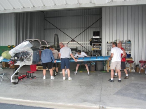
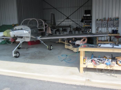
I added a couple extra photos of the wing attachment.