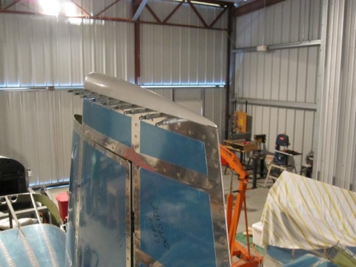
Insert the R-1009 Rudder Tip Fairing into the end of the rudder assembly. I also had to reduce the flange height to 1/2". Push the fairing tightly towards the front and check that the aft end is aligned with the trailing edge of the rudder then match-drill #40 and cleco the rudder tip fairing using the holes in the R-1001 Rudder Skins as a drill guides.
12-3, Steps 1, 2, 4, 5, & 6
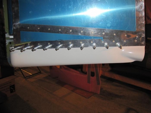
Trim the aft edge of the flange on the R-1011 Rudder Bottom Fairing to remove interference between the flange and the R-1006 Rudder Trailing Edge and allow the fairing to be fully inserted into the bottom of the rudder. Trimming the width of the molded flange may also be required.
Match-Drill #40 and cleco the R-1011 Rudder Bottom Fairing using the holes in the R-1001 Rudder Skins as a drill guides. Work from front towards the trailing edge.
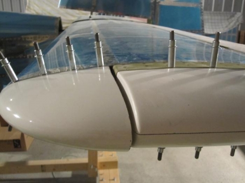
Trim the width of the molded flange on the HS-910 Horizontal Stabilizer Tip Fairing if required to meet the dimensions given. Progressively trim away the aft edge of the horizontal stabilizer tip fairing to leave a minimum 1/8 inch gap between the aft edge of the tip fairing and the forward face of the elevator counterbalance arm. It will be necessary to temporarily attach the elevator to the horizontal stabilizer assembly. I've learned the Van's use of progressively trim is to do this task at least a minimum of a dozen times. I completed the left side and have the right side left to do.
Match-Drill the HS-910 Horizontal Stabilizer Tip Fairing to the HS-1001 Horizontal Stabilizer Skin in a similar manner as the elevator and rudder.