
|

|
|
|
RV-7 Construction Log
|
Date: 11-20-2016
|
Number of Hours: 6.40
|
Manual Reference: p. 8-13, DWG 33
|
Brief Description: Electric Flaps
|
|
I re-drilled the F-785A backrest brace to properly position the attach angle. As it turns out, this was not strictly necessary yet, as that brace is not required to be in place to fit the motor channel.
I tried various methods of positioning the F-767 attach plate and finally came to the conclusion that even though the instructions don't suggest it, at least one F-760 side cover needs to be installed to precisely set the angle of the flap motor channel, and to position the channel relative to the F-705 backrest (photo1). After I figured that out, I marked the attach plate to ensure it got positioned so as to maintain edge distances at both ends.
With the plate clamped to the motor channel, its forward face ended up about 1/8" behind the aft face of the backrest, even with the plate slipped as far down the motor channel as it would go. To prevent having to twist the backrest into position, I decided to fabricate a 0.125" shim to fit between the plate and backrest. After getting everything clamped and drilled, I noticed that the first shim I made was too narrow (about 7/8") to attach the one-legged nutplates. After I made a second one about 1-1/4" wide, everything fit nicely.
I finished the session by prepping and priming the attach plate and shim (photo 3).
|
|
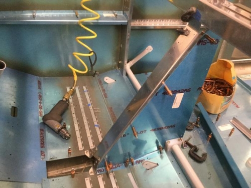
The cover sets the angle and positon of the channel relatve to the backrest.
|
|
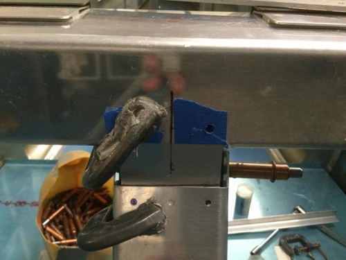
Attach plate with shim clamped in place and ready to drill.
|
|
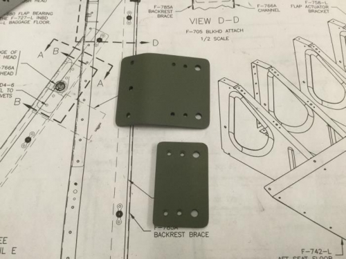
F-767 attach angle and shim primed and ready to rivet.
|
|
|
|
|
|
|
|
|
Copyright © 2001-2025 Matronics. All Rights Reserved.
|