Brief Description: CHT air intake design and creation
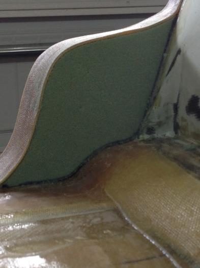
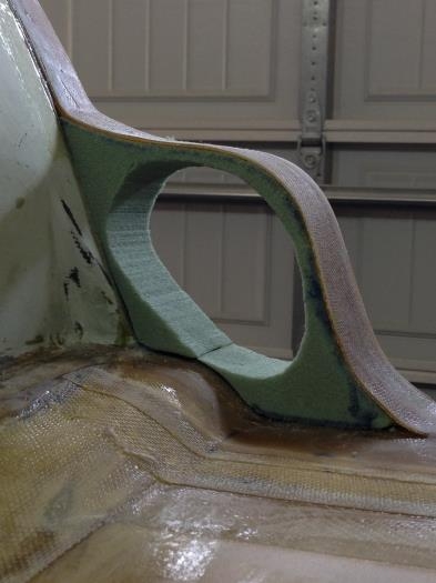
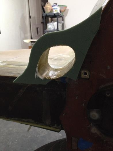
This process looks like it took 10 minutes but it was a half day ordeal. Partly because I went to Lowes and found a 4" PVC Pipe that I was going to use as a template for the intake and it didn't work out. There was no way to squeeze a circle into the opening I had without restricting the opening too much. I opted for an oval shape and will plan on creating my own intake couplers from RTV and BID. I found that using a band saw on the green foam made a very good straight cut. However, green foam is BRITTLE! Man I had to baby this stuff. I stacked a second 2" piece behind the first and CAREFULLY cut out the opening to the rear. I made the opening take a nice gentle curve down in the direction of the cylinders but most of the turn will be done with the RTV. I've calculated the intake openings to be right at about 11 sq in. on either side. I've been reading reports from UL engine owners that are having a hard time getting their CHT's high enough. Like under 300. Good problem to have in my book so I knocked off 1 inch from the standard 12 that lycomings like to have. We will see how it turns out. After spending an hour finessing the openings to death I decided they were alike enough and slurried em up. I then laid up 1 ply BID on the inside. After cure I will have a more stable platform to start agressiviely contouring to the strakes but this foam falls apart looking at it so I will need that BID to keep things in order :) Coming along nicely