
|

|
|
|
Jims RV-8
|
Date: 9-27-2020
|
Number of Hours: 3.00
|
Manual Reference:
|
Brief Description: Panel Plan #1
|
|
Bob has graciously agreed to cut the holes on my instrument panel for the avionics, switches and annunciator lights, so I need to provide exact measurements to him as to where the holes need to be cut and to what size. I spent a while discussing how he went about determining the shapes, sizes and locations of his dimensions, and I will follow suit.
The gist of it is that I will need to draw a replica of my panel, with center reference lines as to where the boxes and other items will go – and then also provide how high and wide each cut will be because the cutting program starts at the 0–0 (zero-zero) reference line and then cuts out from there on each box/appliance. So first, I need to determine where I want to put each appliance, switch and annunciator light – then I need to convert those dimensions into a reference drawing that can be entered into the cutting program. Since the program doesn’t understand, “kinda in the center here, and whatever looks good there” I will have to be precise. I am recalling my freshman year of High School Drafting class…
I dusted off the center panel with the Garmin clings and first needed to determine what the “off-limits” areas would be. The panel is actually in 3 pieces, two permanent side panels that are riveted into place and a larger center panel – that is removable. Since there is structure around each of the 3 panels, there is no mounting in those structural attach areas. So let’s first decide where the “no-zones” are…
|
|
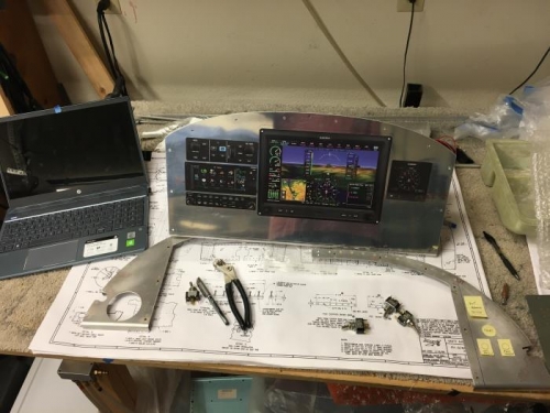
Setup for the discussion with Bob
|
|
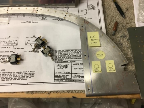
Right side panel prelim
|
|
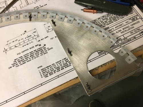
Back side of side panel, note the “no zones”
|
|
|
|
|
|
|
|
|
Copyright © 2001-2024 Matronics. All Rights Reserved.
|