Just doing one aileron at a time here and slowly. The A2 and A5 brackets need to be set in line with each other using micro to secure them and then one ply of BID goes over the top.
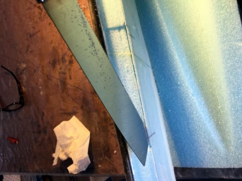
Pic 1 shows cutting the forward slot for the short side of the bracket with the holes. Easy. I inlayed the 3 brackets into the foam but found that the core cut out is not perfect so they were not going to line up on the same plane. We are talking about .05". Sooooo I added back some foam and gave up on the idea of the edges being perfect with the tops of the cores. I can use a little dry micro later.
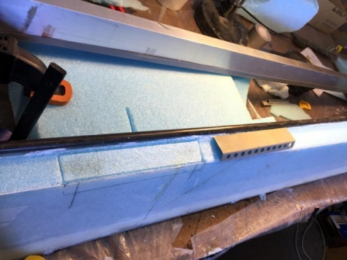
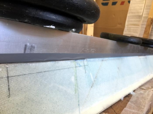
Pic 3 shows the two shorter brackets in place with micro, well you can only see one...in line and weighted for the cure. It took a while to work out the best way to do this as clamps are difficult on these sloping areas. Gravity and weights are fine. Box aluminum is pretty straight.
The result is that I have the two A5 glued in line now and the third longer hinge base is in the right place or in the same plane so its all going to work out. This longer hinge bracket, A2, gets the A10 tube below it, which drives aileron movement and is riveted to the hinge bracket and then the tube in one go. It needs to be touching the bottom of A2 and in the right place for the universal join movement as well as correct motion. I've just measured from the plans drawing, guess thats what they are for...